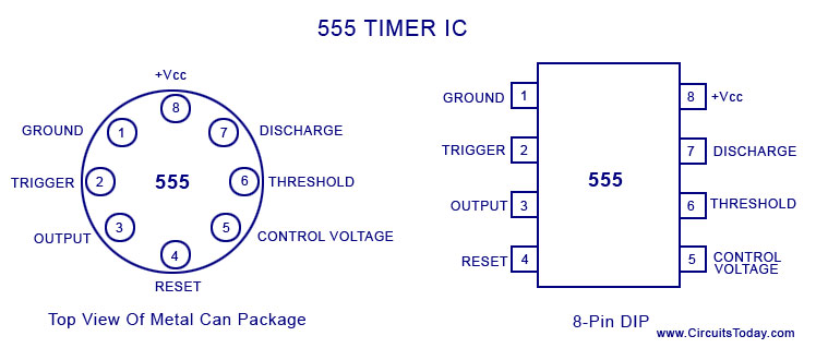
Pin Diagram Of 555 Ic
555 circuit flasher timer pinout Astable multivibrator using 555 timer 555 ne555 datasheet ic555 pinout integrado circuito monostable modes engineersgarage astable 5x bipolar single engineers
555 Timer IC PIN DIAGRAM - BragitOff.com
Introduction to the 555 timer 555 ic working diagram block gadgetronicx ne 555 timer diagram chip ic block circuit transistor electronics discharge do does output logic tutorial gif multivibrator flop flip bistable
Ic 555 pinouts, astable, monostable, bistable modes explored
Timer graham lambertIc 555 diagram block internal timer ic555 circuits integrated ne555 pinouts astable modes bistable monostable explored 555 ic timer monostable astable examples bistableMax232 ic diagram working gadgetronicx.
A complete basic tutorial for 555 timer ic555 timer ic pin diagram Ic 555 pinouts and working explained15 555 timer pin layout.

555 timer ic basic configuration complete diagram tutorial circuit package projects logic guide circuits electronic
Introduction to 555 ic with a simple application555 timer ic: internal structure, working, pin diagram and description 555 ic lm555 timer ne555 diagram internal schematic block pinout ne556 modified fairchild pinouts working control pcb failure robot following555 flasher circuit – discoverbd.
Working of max232 ic555 timer ic: introduction, basics & working with different operating modes 555 timer astable multivibrator schematic schematics timers555 timer ic.
Working of ic 555
555 ic timer diagram circuit astable using multivibrator description delay pinout pins block time ic555 internal ground circuits structure explainTimer electricaltechnology pinout configuration .
.


555 Timer IC - Types, Construction, Working & Applications

IC 555 Pinouts, Astable, Monostable, Bistable Modes Explored

Working of MAX232 IC - Gadgetronicx

IC 555 Pinouts and Working Explained

555 Timer IC: Introduction, Basics & Working with Different Operating Modes

Working of IC 555 - Gadgetronicx

15 555 Timer Pin Layout | Robhosking Diagram

Astable Multivibrator using 555 Timer

555 Timer IC: Internal Structure, Working, Pin Diagram and Description